close
Getting Started with Desktop CNC
Making circuit boards at home (aka trials and tribulations in isolation routing)
settings TinkeringI’m embarrassed to admit that my 3018 desktop mill had been collecting dust since I received it as a Christmas gift in 2018, largely due to my open project backlog (and a busy year between work travel, getting married, and moving back to Boston). But, following that recent move (and after putting a dent in the project backlog), I finally had enough downtime around work travel to put some nights and weekends toward getting it up and running.
My efforts broke down into the following categories:
- Hardware upgrades (limit switches, waste boards, and 3D printed fixturing)
- Software toolchain (KiCad, pcb2gcode, some custom gcode generation scripts, and Universal Gcode Sender)
- Experimentation (testing feeds & speeds, breaking some bits, etc.)
Hardware Upgrades
Installing Limit Switches
My first priority was adding limit switches to prevent accidentally slamming into the end of an axis/grinding the stepper motors, with the added benefit of also enabling homing. Pretty much any three pin limit switch will do the trick here – I had a bag of these laying around. The grbl wiki does a good job of explaining the basic styles of switches and corresponding wiring schemes. I used the “normally open” wiring scheme which is about as simple as it gets:
- Two switches per axis, times three axes (x, y, z)
- Two wires per switch: one on the pin closest to the lever arm pivot (COM pin) and one on the middle pin (NO pin)
- The control board has two pairs of pins for each axis. As the pins are labeled, wiring is self-explanatory.
I designed some 3D printed mounts to affix the limit switches to the mill frame. It’s worth noting that I took an unorthodox approach here, opting for a cradle/clamp around the plastic body of the switch assembly, rather than screwing the switch’s through-holes. I only did this because none of the standard hardware I keep on-hand was compatible with the switches and I was impatient to move things along.
When running the wiring, I made sure to leave plenty of length in the wires to both account for the distances of the mounting positions from the control board and the fact that the z-axis switches need enough slack for the z-carriage to move up and down while also sliding back and forth across the x-axis. The x- and y-axis mounts are easy to connect directly to the metal frame using extra hardware included with the mill. To mount the z-axis switches, I just glued them to the plastic body of the z-carriage (and clamped them for 24 hours to get a strong cure). Five of the six switches, as well as my approach to wire management (twist wires, tuck in extrusion channels, and zip tie in place), are visible in the shot below:

With the switches wired and mounted, I next needed to update the machine’s settings to actually enable monitoring of the switches. In Universal Gcode Sender (my machine controller of choice; more on this in the discussion of software toolchain), enabling limit switch monitoring is as simple as sending command $21=1 to the machine. This is also a good place to go ahead and enabled homing with $22=1. With those two options enabled, sending a $H command will home all of the axes, testing the switches in the process.
Outside of homing commands (manually “jogging” the machine, running a poorly placed job, etc.), when a limit switch is triggered the spindle will stop spinning and the board “locks” to prevent further movement. To start moving again, the mill must be reset and unlocked – this can be accomplished through the GUI or with successive Ctrl-X and $X commands in the console. The first move away from the end of the axis often retriggers the switch. When it does, the same process of reseting and unlocking the machine needs to be repeated.
While testing the homing capability, I noticed that some of axes weren’t oriented how I’d like. Fortunately, there’s an easy fix, as axis inversion is controlled in GRBL with an 8-bit bitmask (of which only the three least significant bits are used). Starting from the least significant bit, the bits control, in order, inversion of the x-axis, the y-axis, and the z-axis. For example, a bitmask of 00000101 inverts the x and z axes, while 00000011 inverts the x and y. The mask can be sent via the console in the format $3=00000101, or, more simply, $3=5.
Waste Boards
Installing a waste board was my next step in “protecting the machine from itself” (since it’s effectively a dumb terminal). Between the risk of dropping bits while changing them, accidentally cutting or drilling too close to the platform, or simply trying to cut all the way through a piece of material, there are plenty of reasons to put softer sacrificial material between the cutting head and the the aluminum build platflorm. I opted for MDF, as it’s cheap and relatively flat, smooth, and uniform – a quick trip to Home Depot for a 24x48” sheet of 1/4” thick MDF set me me back about four bucks.
At home, I used a circular saw and a straight edge to rip the sheet (across the 24” dimension) into 11” strips and then cross-cut those to 7”, approximating the footprint of the mills’s build platform. I then struck a 4.5cm grid onto the cut pieces (to correspond with the spacing of the build plate’s slotted rails) and drilled a grid of through holes for mounting the plate to the build platform (with plenty of holes leftover for fixturing). As I had a ton of M5 machine screws laying around, whose heads were almost the perfect size for the build plate’s slotted rails, I pre-drilled all of the holes with a 5/64” bit before finishing them at 7/32”. As MDF has a tendency to “blow out” or sort of delaminate on the backside while drilling through, I made sure to clamp the work-in-progress wasteboards to a (secondary) wasteboard for the drilling process.

This will be covered in more detail in subsequent sections, but, I’ll likely take a differnt approach in future iterations. The through holes are a bit of a pain because they require first sliding the mounting bolts into the build plate’s rails, getting them roughly in place relative to the waste board’s grid, and then getting the waste board to slide down onto them. And, whenever I want to change up fixturing locations, I have to remove the entire wasteboard to move the mounting bolts around in the rails.
Slots that extend to the ends of the waste board would make this process much smoother. Fortunately, now that I have a functional enough set of waste boards in place, I’ll probably experiment with using the mill itself to produce future waste boards, with the additional benefit of being able to make some surfacing passes to get the surface perfectly planar with the mill’s working plane.
3D Printed Fixtures
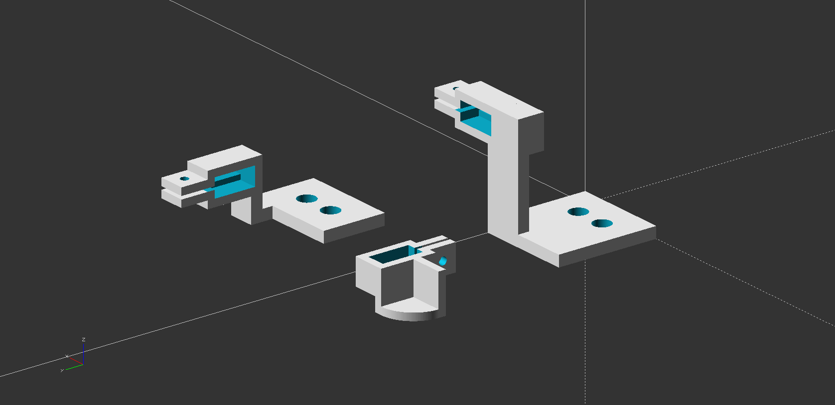
A great thing about having a couple 3D printers on-hand is that I can quickly and easily produce purpose-designed fixturing hardware for whatever I’m trying to mill. For isolation routing circuit boards, I designed some notched lever arms to clamp the edges of the circuit board blanks, along with some general purpose knobs for holding down both the clamps and the waste board, as well as some blocks to take up the slack around the mounting bolts heads placed in the build plate’s slotted rails.
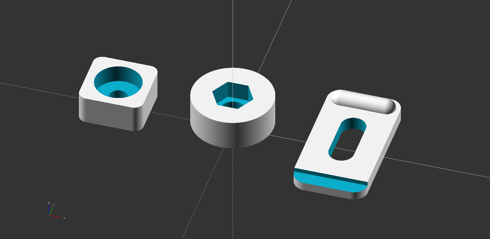
I press fit the M5 nuts and bolts into the knobs and blocks, respectively, and put it all together. Aside from the aforementioned challenges in assembly mechanics, everything fit together perfectly, the knobs are a breeze to adjust, and, in my subsequent circuit board attempts, everything held in place perfectly.

Software Toolchain
With all of the hardware preparations out of the way, I turned my attention to the software side. Whether doing additive desktop manufacturing (3D printing) or subtractive (milling), the basic flow from design to manufactured part remains the same. I’ve outlined the process below, with examples for both the fixturing jigs that I 3D printed for this project, as well as the milled circuit boards.
- Generate a design in a CAD (computer-aided design) program
- Solid part: OpenSCAD
- Circuit board: KiCAD
- Export the design from the CAD program
- Solid part: exports as .stl
- Circuit board: exports as a series of .gbr (gerber) and .drl (drill) files for the top and bottom layers of the board
- Use a CAM (computer-aided manufacturing) program to translate the exported design into instructions for the machine
- Solid part: Cura, a slicer, takes parameters like nozzle size, print speed, and layer heights to “slice” the solid model into a series of instructions for the 3D printer to move in x/y/z space while extruding material at particular speeds and temperatures
- Circuit board: pcb2gcode, a command line utility, takes parameters like mill size, feed rates, and spindle speed to convert circuit board layers into a series of instructions for the mill to move in x/y/z space while spinning the spindle at particular speeds
- In both cases, the “instructions” for the machine are G code
- Manufacture the design by sending those instructions to the machine
- Solid part: Cura can also send instructions directly to the machine, or I can load the instructions on an SD card that is inserted into the printer
- Circuit board: The G code files are opened in Universal GCode Sender, which then sends commands along to the mill one line at a time
KiCad
To keep things brief here, I designed my circuit schematic, defined physical footprints for the circuit components, created a mapping between the physical pins/pads and the schematic, layed out the physical components on a board, and manually routed the connections. In finishing the board design/layout, I also defined some through holes to be used for mounting the finished circuit board in an enclosure, as well as the outline of the board to be routed (as indicated by the thin yellow lines below) out of the larger circuit board blank.

As I’m used to designing boards with fine pitch components for board houses with very precise capabilities, I had to take a step back, consider the capabilites of my machine, and adjust my design accordingly (and with some trial and error to get a feel for realistic precision). In addition to a conservative use of exclusively through-hole components, I also kept every pad’s smallest dimension above 1.8mm, sized all through-holes to 1.1mm, made all traces 1mm+ thick, and made sure I kept the layout loose enough to allow at least 1mm of space between traces.
It’s worth noting my use of the “auxiliary axis”, which I placed at the center of my board. Because my circuit board blanks have two copper layers, I have to mill both sides, even with a single layer design, to make sure all of my through holes remain isolated from one another unless explicitly connected with a trace. Placing the auxiliary axis on the center of the board makes for “tighter flipping” – that is, it makes it much easier to consistenly fixture the board, mill one side, flip it, and mill the other side, while maintaining consistent placement and alignment throughout the process.
Once I was happy with my board design, I clicked the “Plot” option in KiCAD, specified the directory for my export (/gerbers), enabled “use auxiliary axis as origin”, and made sure all of my important layers (F.Cu, B.Cu, and Edge.Cuts) were selected. After clicking “Plot” and “Generate Drill Files”, and all of the .gbr and .drl files needed to make my board were ready in the specified directory.
pcb2gcode
With pcb2gcode as my selected tool for generating G code, I created a millproject file and ran pcb2gcode from the same directory. The millproject file defines sources for the various board layers, defines the bits I’ll be using for the milling process, corresponding feeds and speeds, and other general paramters for milling. Full documentation of all of these parameters can be found here (and was very helpful while I muddled my way through this for the first time). My millproject file is included below, reflecting the parameters that yielded the best results following several iterations of botched boards and broken bits.
# Sources
front=gerbers/alexa-earmuffs-F_Cu.gbr
back=gerbers/alexa-earmuffs-B_Cu.gbr
drill=gerbers/alexa-earmuffs-PTH.drl
outline=gerbers/alexa-earmuffs-Edge_Cuts.gbr

# Common options
metric=true
zsafe=1
zchange=5

# Mill options
# 30 degree v-bit
zwork=-0.5
mill-diameters=0.7
mill-feed=5
mill-vertfeed=5
mill-speed=3000

# Drill options
# 1.1mm end mill
milldrill-diameter=1.1
zdrill=-2.2
drill-feed=5
drill-speed=3000
drill-side=back
nog81=true
onedrill=true

# Outline options
# 1.2mm end mill
cutter-diameter=1.2
zcut=-2.2
cut-feed=5
cut-vertfeed=5
cut-speed=3000
cut-infeed=0.3
cut-side=back
bridges=10
bridgesnum=8
zbridges=-1.5
Custom gcode Generation Scripts
While pcb2gcode is very effective at spitting out solid G code, I found that my particular machine was choking on a couple non-critical lines in the generated files. Between that and some other papercuts in the process, I resolved to whip up a little shell script to further streamline the process for myself. The script does the following:
- Leverages a second
millprojectfile (calledmillproject-predrill) to to generate a pre-drilling operation on all through holes using a smaller bit that’s less prone to walking - Captures board dimensions from pcb2gcode’s output, to define additional through holes to be drilled for flip-flop fixturing purposes
- Renames G code files in sequential order to idiot-proof my process of feeding the files to the mill
- Removes the chunks of G code that my particular machine has trouble with
- Cleans up some extraneous files generated by pcb2gcode that I don’t care about
The full contents of the affectionately-named drillbabydrill.sh file are shown below:
# Execute pcb2gcode against the pre-drill millproject
mv millproject millproject-temp
mv millproject-predrill millproject
pcb2gcode &>/dev/null
echo "\n- Generated pre-drill file"

# Execute pcb2gcode against main millproject, capturing output
mv millproject millproject-predrill
mv millproject-temp millproject
mv drill.ngc predrill.ngc
check=$(pcb2gcode)
echo "\n- Generated mill and drill files"

# Rename files in use sequence & move to sub-directories
mv front.ngc 3_front.ngc
mv back.ngc 4_back.ngc
mv predrill.ngc 5_predrill.ngc
mv drill.ngc 6_drill.ngc
mv outline.ngc 7_outline.ngc
mv *.ngc gcode
mv *.svg svg

# Parse board height and fill fixturing template
height=$(echo ${check} | sed "s/.*Height\: \([0-9]*\.[0-9]*\)in.*/\1/")
height=$(echo "scale = 5; (${height} + 1) / 2" | bc)
predrill="0.08661"
drill="0.19685"
cp fixture-template.gcode gcode/1_predrill.ngc
cp fixture-template.gcode gcode/2_drill.ngc
sed -i -e "s/\<y\>/${height}/g" gcode/1_predrill.ngc gcode/2_drill.ngc
sed -i -e "s/\<d\>/${predrill}/g" gcode/1_predrill.ngc
sed -i -e "s/\<d\>/${drill}/g" gcode/2_drill.ngc
echo "- Generated fixturing files"

# Remove lines from gcode that 3018 chokes on & clean up
sed -i -e '13,19d' gcode/3*.ngc
sed -i -e '13,19d' gcode/4*.ngc
sed -i -e '13,19d' gcode/7*.ngc
sed -i -e '9d' gcode/3*.ngc
sed -i -e '9d' gcode/4*.ngc
sed -i -e '9d' gcode/7*.ngc
sed -i -e '12,18d' gcode/5*.ngc
sed -i -e '12,18d' gcode/6*.ngc
echo "- Cleaned mill and drill files for 3018"

# Clean up troll files
rm -rf gcode/*.ngc-e

# Finished
echo "\nDONE.\n"
To make the script generally-available, regardless of the working directory (as I definitely have more than one circuit board project I’ll want to use it on), I renamed it and ran the following commands in Terminal to make it executable via pcb2gcodeplus from any directory.
mv pcb2gcodeplus.sh /usr/local/bin/pcb2gcodeplus.sh
sudo vim /etc/paths # add /usr/local/bin
chmod +x pcb2gcodeplus.sh
Running the script in my project-specific directory generates a nested /gcode directory with the following contents:
1_predrill.ngc  (Pre-drill for flip-flop fixturing)
2_drill.ngc     (Full drill for flip-flop fixturing)
3_front.ngc     (Front pads and traces)
4_back.ngc      (Back pads and traces; flip board prior to this step)
5_predrill.ngc  (Pre-drill through-holes)
6_drill.ngc     (Full drill through holes)
7_outline.ngc   (Mill board outline)
Universal Gcode Sender
Milling is now as easy as putting a blank on the mill, using my multimeter (in continuity mode, with one lead connected to the mill bit and one lead connected to the copper circuit board blank) to zero the z-axis, and dropping in the successive files to be run. After the first two drilling steps, I dropped in thumb tacks to further fixture the board – these holes are important for indexing against once it’s time to flip the board and mill out the other side.

Experimentation
Milling Attempts
My millproject file included above shows what worked, but here’s a list of some of the things that definitely didn’t work along the way:
- A 0.4mm end mill with 100 vertical feed flexed and broke when making contact with the board on descent.
- A 0.5mm end mill with 10 vertical feed and 30 horizontal feed punched in okay on descent, but flexed and broke upon first horizontal movement.
- A 60 degree v-bit with 10 vertical feed and 30 horizontal feed worked great until it got sucked into an adjacent hole and snapped off the tip – it was at this mount that I realized I’d 1) knocked my jig out of alignment between operations and 2) ought to mill pads and traces prior to drilling through holes.
- All of my circuit board blanks proved to be lightly warped, resulting in a bit of a pop/flex when bits entered. However, this was less of an issue for broken bits than the tendency of the end mills to walk prior to breaching the first copper layer, leaving them in a pre-flexed position prior to beginning horizontal movement.
Despite the handful of broken bits and false starts, it was a thing of beauty once I got it dialed in (and realized that, among the bits I had on-hand, v-bits were going to give me the cleanest results).

Routing the edges with a nice fat 1.1mm end mill worked fantastically, generating a clean edge through the entire thickness of the board, while leaving paper-thin tabs to keep the board in place.

Despite initially clean results, burring did become a bit of a problem as milling continued. I did my best to clean things up with an Olfa knife, but still ran into a lot of problems with shorts (lack of solder mask didn’t do me any favors either).

The waste board worked great and is still in smooth enough shape after multiple boards that it looks like I can get decent mileage per waste board by just lightly adjusting placement between milling attempts.

Takeaways
- If I’m going to mill boards from start to finish, I should just buy some one-sided circuit board blanks to cut my process time in half and eliminate the flip-flop.
- Buying higher-quality broader-angle v-bits should help with burring issues.
- For better (and potentially quicker) results, I intend to explore a hybrid approach that of chemical etching for pads and traces before milling through holes and edges.
- I definitely need to get some solder mask – liquid application looks like a bit of a pain versus dry film options, but I’ll probably try both.
For now, I’m back on the road for work, but, as soon as I can get some quality time back in the workshop (aka my clutterd desk in the living room of our one bedroom apartment), I look forward to seeing what kind of results these process improvements can yield.